- All
- Product Name
- Product Keyword
- Product Model
- Product Summary
- Product Description
- Multi Field Search
English


Views: 0 Author: Site Editor Publish Time: 2026-10-12 Origin: Site


Machining heat-resistant superalloys presents severe metallurgical hurdles for any shop floor. When you cut this material, the high nickel and chromium content causes rapid work-hardening and extreme heat retention. Instead of heat evacuating with the chip, it transfers directly into your cutting tool. This thermal dynamic leads to catastrophic insert failure, poor surface finishes, and blown dimensional tolerances. Scrapping parts at this stage creates massive production bottlenecks. To successfully process a inconel 718 plate, you need a strict technical framework. You must evaluate the right cutting methods, select specific tooling geometries, and dial in aggressive feeds and speeds. This approach prevents the material from hardening ahead of the tool and ensures clean, repeatable cuts.
Tooling Geometry is Critical: Clean cuts require sharp, positive cutting edges (edge radii below 15 µm) rather than honed or chamfered edges to slice the material instead of deforming it.
Aggressive but Controlled Parameters: Successful machining demands low surface speeds combined with reasonably heavy depths of cut and high feed rates to get under the work-hardened layer.
Thermal Management: Because Inconel 718 does not dissipate heat well, high-pressure coolant delivery directly to the cutting zone is mandatory to prevent tool degradation.
Process Selection: The optimal cutting method (Waterjet, Laser, EDM, or CNC machining) depends heavily on the thickness of the plate, required tolerances, and heat-affected zone (HAZ) limitations.
Defining success dictates your entire machining strategy. A truly clean cut in superalloys goes far beyond hitting a dimensional tolerance on a print. You must maintain the structural integrity of the base metal while achieving the required geometry. On the shop floor, we evaluate a clean cut based on four strict criteria:
Complete absence of burr formation along the exit edge of the tool path.
Zero micro-cracking within the crystalline structure of the machined surface.
Base material hardness remains completely unaltered by the mechanical cutting forces.
Target surface roughness (Ra) is achieved without smearing or tearing the metal.
Meeting these criteria requires overcoming the alloy's metallurgical heat retention. Standard carbon steels absorb heat into the chip. The chip curls, breaks, and carries thermal energy away from the cutting zone. Superalloys reject this process. The high nickel and chromium matrix creates a powerful thermal barrier. Heat cannot escape through the chip, so temperatures at the cutting edge rapidly exceed 1000°C. This intense heat blasts directly into the carbide or ceramic tool substrate. The cobalt binder within the carbide begins to break down, leading to plastic deformation of the cutting edge and immediate tool failure.
Strain-age hardening presents an equally destructive mechanical challenge. This material possesses exceptionally high shear strength. As the cutting edge attempts to shear the metal, the underlying crystalline structure deforms. This mechanical deformation causes immediate, localized work hardening. If your tool rubs against the workpiece instead of slicing cleanly, the surface hardness spikes instantly. Dwelling during a cut destroys the part. The next tool pass will hit a layer significantly harder than the base metal, causing the end mill to deflect, chatter, and shatter. Your depth of cut must always exceed this work-hardened layer to keep the tool engaged in softer, virgin material.
Industrial profiling of a Inconel 718 Nickel Alloy Plate requires matching the cutting method to the material thickness and specific tolerance requirements. No single process fits every application. You must evaluate the primary industrial methods for parting and profiling plate stock to select the most efficient approach for your specific part geometry.
Abrasive waterjet cutting serves as the most effective method for thick plate profiling. Industrial pumps generating 60,000 to 90,000 PSI force water and garnet abrasive through a tiny sapphire or diamond orifice. The primary advantage is the complete absence of a Heat-Affected Zone (HAZ). Because the process relies on cold mechanical erosion, zero work hardening occurs. The material properties remain entirely intact. However, edge taper is a known limitation on plates exceeding one inch in thickness. You will typically need secondary CNC machining to square the edges and hit tight dimensional tolerances.
Fiber laser cutting excels when processing thinner stock. It is highly effective for profiling Inconel 718 Sheet and Inconel 718 Precision Strip. Modern high-wattage fiber lasers cut rapidly, but they introduce specific thermal risks. Localized melting and dross accumulation on the bottom edge happen frequently if focal lengths are incorrect. Micro-cracking at the cut edge occurs if thermal input is not strictly controlled. High-pressure nitrogen assist gas is absolutely mandatory. Using oxygen causes exothermic reactions, leading to burnt edges and severe oxidation. Nitrogen shields the molten pool, resulting in a clean, weld-ready edge.
Wire Electrical Discharge Machining (EDM) provides the ultimate solution for high-precision, complex geometries. When mechanical cutting forces would distort a thin plate, EDM relies on spark erosion. A brass or zinc-coated wire passes through the material submerged in dielectric fluid. You achieve extremely high accuracy and pristine edges, but processing speeds are exceptionally slow. Wire EDM is typically reserved for critical aerospace components where tolerances are measured in microns and mechanical stress is strictly prohibited.
Fabrication alternatives often outperform traditional billet machining. Hogging out deep cavities from a single solid block wastes expensive material and consumes massive amounts of machine time. Internal machining stresses also cause significant warping as material is removed. Instead, consider welding pre-cut plates to form complex structures. Fabricate a three-plate assembly first, then post-machine the critical holes and mating surfaces into their exact locations. This strategy drastically reduces overall machining time, minimizes tool wear, and virtually eliminates material waste.
| Cutting Method | Best Application | Primary Advantage | Main Limitation |
|---|---|---|---|
| Abrasive Waterjet | Thick plate profiling (1"+) | Zero HAZ, no work hardening | Edge taper requires secondary machining |
| Fiber Laser | Thin sheet and precision strip | High processing speed | Risk of micro-cracking and dross |
| Wire EDM | Complex, high-tolerance parts | Extreme accuracy, no mechanical force | Very slow cutting speeds |
| CNC Milling | Final dimensioning and features | Excellent surface finish control | High tooling costs, rapid tool wear |
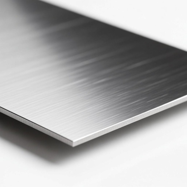
Milling or turning this superalloy requires exact tooling specifications. Generic carbide end mills will fail within minutes. You must evaluate tooling based on substrate, coating, edge preparation, and core strength to achieve predictable outcomes on the machine.
Substrate and coating selection dictate thermal resistance. Solid carbide tools with sub-micron grain structures (typically 10% to 12% cobalt content) perform exceptionally well for roughing operations. The fine grain prevents micro-chipping at the cutting edge under heavy loads. For high-speed finishing, ceramic inserts like Sialon or whisker-reinforced ceramics excel. They withstand massive heat, allowing for much higher surface speeds. Titanium Aluminum Nitride (TiAlN) or Aluminum Titanium Nitride (AlTiN) coatings provide an essential thermal barrier for carbide tools. At high temperatures, these coatings oxidize to form a protective aluminum oxide layer, shielding the carbide substrate from thermal shock.
Edge preparation is the most critical geometric factor. Sharp, positive cutting edges are mandatory. Honed or heavily chamfered edges push the material rather than shearing it. This pushing action causes immense friction, generates heat, and triggers rapid work hardening. You must maintain edge radii below 15 µm. Tooling geometries optimized for austenitic stainless steel often serve as an excellent, proven baseline. They share the need for sharp, positive shearing action to cut cleanly through heat-resistant materials.
Flute count and core strength determine tool rigidity. Rigidity is everything when cutting high-shear-strength alloys. Tool deflection causes chatter, which destroys the cutting edge and ruins the surface finish. We recommend using 4-flute to 6-flute solid carbide end mills. These tools must feature thick core diameters, ideally exceeding 60% of the total tool diameter. A thicker core resists bending moments during heavy cuts. Variable pitch and variable helix designs are also highly recommended. They break up harmonic frequencies, preventing chatter and stabilizing the cutting process during heavy engagement.
Implementation realities require strict discipline on the shop floor. You cannot rely on standard machining formulas used for steel or aluminum. You must adapt your parameters to manage heat and prevent work hardening simultaneously.
Spindle speed and Surface Footage per Minute (SFM) must be strictly controlled. You must turn down the spindle. Keeping SFM low is the only way to manage heat generation at the cutting edge. For standard solid carbide end mills, baseline recommendations sit around 90 to 150 SFM. This translates to roughly 700 to 1100 RPM for a half-inch diameter tool. Pushing the RPM higher will instantly burn the coating off the tool, leading to immediate plastic deformation of the carbide substrate. Ceramic tools operate differently, requiring speeds between 600 and 1000 SFM to generate the heat necessary to plasticize the shear zone.
Depth of Cut (DOC) and feed rates require an aggressive approach. The golden rule is to never rub the tool. You must apply higher feed rates to ensure the tool actually cuts. Target a baseline of roughly 0.0015 to 0.003 inches chip load per flute. Combine this with reasonably heavy depths of cut. The cutting edge must penetrate below the work-hardened zone left by the previous pass. If you take light, tentative cuts (under 0.010 inches), the tool will rub against the hardened surface, generating massive heat and failing prematurely.
Coolant strategies make or break the operation. Standard flood coolant is entirely inadequate. At the temperatures generated during this process, low-pressure coolant boils before it ever reaches the cutting edge. It creates a vapor barrier that blocks further cooling. High-pressure, through-tool coolant operating at 1000+ PSI is required. This high-pressure stream pierces the vapor barrier and blasts steam away from the cutting zone. Furthermore, it provides severe thermal shock to the chip, causing it to break and evacuate instantly. Maintain coolant concentration between 10% and 12% to ensure adequate lubricity.
| Tool Material | Operation Type | Surface Speed (SFM) | Feed per Tooth (IPT) |
|---|---|---|---|
| Sub-micron Carbide | Rough Milling | 90 - 120 | 0.0015 - 0.0025 |
| Sub-micron Carbide | Finish Milling | 120 - 150 | 0.0010 - 0.0020 |
| Sialon Ceramic | Rough Turning | 600 - 800 | 0.0040 - 0.0080 |
| Whisker Ceramic | High-Speed Milling | 800 - 1000 | 0.0030 - 0.0050 |
Balancing tool life, cycle time, and part quality requires strategic planning. Process mitigation ensures that when variables change, the machining operation remains stable and predictable. You must balance the cost of tooling against the cost of machine time. Sometimes, running parameters slower saves thousands of dollars in carbide inserts. In other scenarios, pushing ceramic tools to their absolute limit increases throughput enough to justify the higher tooling costs.
Manual lathe limitations must be acknowledged. Turning superalloys on manual equipment is highly discouraged. Human hands simply cannot maintain a perfectly constant, aggressive feed rate. Micro-pauses in the feed cause the tool to dwell. Dwelling instantly hardens the part. This leads to inevitable work hardening and catastrophic tool failure. CNC equipment provides the uninterrupted, constant chip loads required to shear the material cleanly.
Tool path strategies heavily influence heat distribution. Always use climb milling over conventional milling. Climb milling pushes the thickest part of the chip first, absorbing the heat. The chip then thins out as the tool exits the cut. Implement dynamic milling or trochoidal tool paths. These strategies maintain a constant radial chip thinning effect. They keep tool engagement low, typically between 5% and 10% radial depth of cut, while utilizing the entire flute length. This distributes heat evenly across the tool and prevents localized notch wear at the depth of cut line.
Monitoring tool wear requires strict protocols. Establish mandatory tool changes based on time in the cut. Running a tool until failure often destroys the workpiece. When a tool shatters, it embeds carbide fragments into the hardened superalloy. Removing these fragments is nearly impossible without scrapping the part. Implement the following wear monitoring steps:
Establish a baseline time-in-cut limit using scrap material before running production parts.
Inspect cutting edges for flank wear exceeding 0.008 inches, replacing inserts immediately when reached.
Check for notch wear at the depth of cut line, which indicates excessive heat concentration.
Monitor spindle load meters; a sudden spike in load indicates the cutting edge has degraded.
Cutting this advanced superalloy cleanly requires a rigid setup, strict thermal management, and an absolute commitment to sharp tooling. Aggressive feeds combined with low surface speeds prevent work hardening and ensure dimensional accuracy. To implement these strategies effectively on your shop floor, follow these immediate next steps:
Audit your machine's coolant delivery system to ensure it consistently outputs at least 1000 PSI through the spindle.
Standardize your tool change intervals based on strict time-in-cut metrics rather than operator feel or visual inspection.
Run a baseline dynamic milling test on scrap material to dial in your radial engagement and chip thinning calculations.
Transition all roughing operations to variable-pitch, sub-micron carbide end mills with AlTiN coatings.
A: While technically possible, it is highly discouraged. Manual machining cannot maintain the heavy, constant feed rates required to prevent work hardening. Any hesitation or dwelling by the operator instantly hardens the surface, leading to rapid tool failure and ruined parts. CNC equipment is strongly preferred to maintain constant chip loads.
A: High-lubricity, water-soluble coolants are the best choice. Maintain a concentration between 10% and 12%. They must be delivered at high pressure, exceeding 1000 PSI, directly through the tool. This high pressure is necessary to pierce the thermal vapor barrier, cool the cutting edge, and evacuate chips instantly.
A: Prevent work hardening by using extremely sharp, positive cutting edges and maintaining an aggressive feed rate. Never allow the tool to dwell or rub against the material. Ensure your depth of cut is always deep enough to get under the work-hardened layer left by the previous pass.
A: A conservative baseline is 0.0015 to 0.003 inches per tooth. This ensures the tool shears the material rather than rubbing. However, this must be adjusted based on the specific tool diameter, core strength, radial engagement, and the overall rigidity of your machine setup.
A: Yes, but it requires strict thermal control. Use modern fiber lasers equipped with high-pressure nitrogen assist gas. The nitrogen prevents exothermic oxidation and shields the cut. Proper fixturing and optimized cutting speeds are also required to manage heat input and prevent thermal distortion in thin strips.
A: Dedicated heat-resistant superalloy tooling is always best. However, geometries designed for austenitic stainless steel often feature the sharp, positive cutting edges required to shear superalloys. They serve as a very strong starting point if specialized aerospace tooling is unavailable in your shop.


